Procedural Planets in Unreal Engine 5 - Part 3

Introduction
It’s been quite some time since I last worked on the planet project, and I wouldn’t blame anyone for thinking this series had been abandoned. However, giving up is not something I’m inclined to do—I just needed time—a lot of time, it seems—to recharge. In the last entry on planets, I mentioned that part 3 would cover the importance of good tooling and visualization, and that hasn’t changed. In addition, what we’ll be building might look a bit daunting at first—especially to newcomers—but is ultimately fairly straightforward. This tutorial also won’t require any C++, which was intentional; iteration is simply much faster in Blueprint, and I took it as a personal challenge to see if this tool could be made entirely in Blueprint.
What are we making?
So what will we be building, and does it relate to planets at all? Yes, the tool relates to planets, and what we'll be building is an editor based quadtree visualizer. For the newcomers asking "what the **** is a quadtree?", I will attempt to explain this as simply as I can: quadtrees are a way to manage data by partitioning certain data sets into smaller parts repeatedly. For relevant context (meaning a player moving along a landscape), imagine you have a single square - nothing in it whatsoever, you just have an outline of the shape - and as you approach it, it splits into 4 smaller but equal size squares. As you get closer to one of the new squares, it splits into 4 smaller squares. You keep repeating this logic until you hit a predefined threshold, and that's it, really. What you do with the data structure is up to you. That basic formula is what we're going to be following today, as it's a quadtree in its simplest form, in my experience, anyway. That said, I recommend exploring the topic further on your own as quadtrees have a wide range of applications beyond what we’ll be using them for, which is serving as an efficient way to implement LODs for our planet.
The reason I've chosen a quadtree visualizer is that we can kill two birds with one stone, really; I wanted to drive home to aspiring TAs how important good tooling/visualizers can be when approaching an unfamiliar task/topic, and I also wanted to make good progress towards the planets themselves. In this case, I had never implemented a quadtree before, and rather than make it hard for myself by attempting an implementation with existing mesh logic, I opted to create a more transient debug system. What I mean by that is I don't keep explicit track of the root/children or any data related to them, really, and I especially did not want to deal with vertices or normal seams across nodes while learning the basics. The whole point of this visualizer is to assist with learning how quadtrees work in a hands on environment but without extraneous things getting in the way. With that longwinded explanation out of the way, let's get into the specifics of this blueprint only challenge.
Asset creation and setup
If you've spent time with editor tooling, you likely know that actors don't tick outside of PIE - this is a problem as we need to be able to update our quadtree actor at editor time. This can be resolved, but it is not intuitive; luckily, I am here to enlighten you, dear reader.
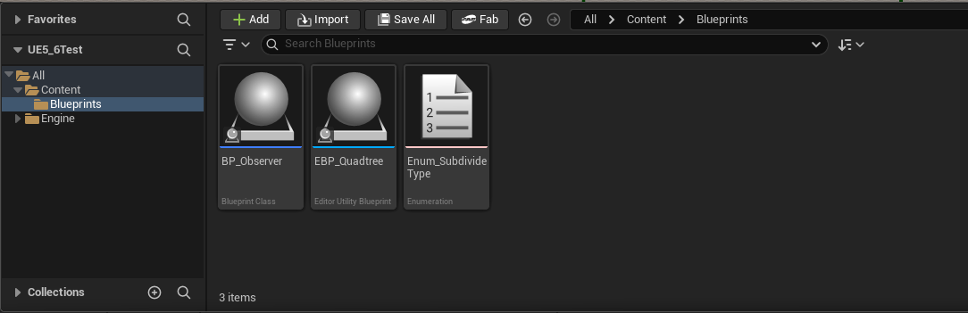
- To begin, right click in the content browser, browse to "Editor Utilities", and click "Editor Utility Blueprint". A window will pop up, and you will need to select "Editor Utility Actor". Name this something like "EBP_Quadtree". You'll want to add a "Box Collision" component to it in the component list and scale it up to a good size.
- We will also need an enum, so go ahead and make one called "Enum_SubdivideType". Add in two entries called "Camera" and "Observer", respectively.
- Finally, we need something to act as our observer actor. For simplicity, I opted to create a standard blueprint actor with a billboard as the scene root. If you like, you could simply create an actor in your level and give it a tag. The choice is yours.
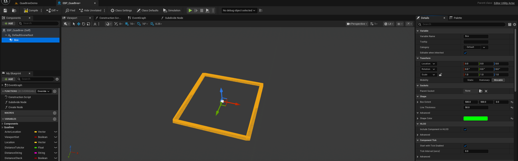
This is a good start, and while it may seem intuitive to think that an editor actor will do what we want in terms of ticking by default, it will not. There are a few things we need to setup first before we're in business:
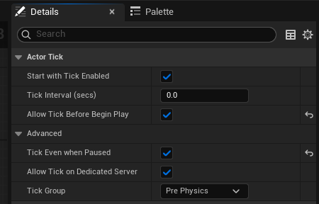
- With your quadtree BP open, select "Class Defaults" at the top of the tab. This should open a details panel.
- From here, set the tickboxes for "Allow Tick Before Begin Play" and "Tick Even When Paused" to true.
Actor references
So, now we have to start building out all of our logic. The first thing we'll start with is the construction script. Earlier, I said to make a decision on how you want to handle your observer actor, and the reason is that we want to store a reference to that actor for use outside of the construction script. I'm grabbing the reference here in the quadtree construction script because the CS isn't being ticked constantly like the rest of our logic will be later, which is good as I don't want to constantly be grabbing the reference. So, here is an example of what you can do to store the reference (though it is just an example, and is not the only way):
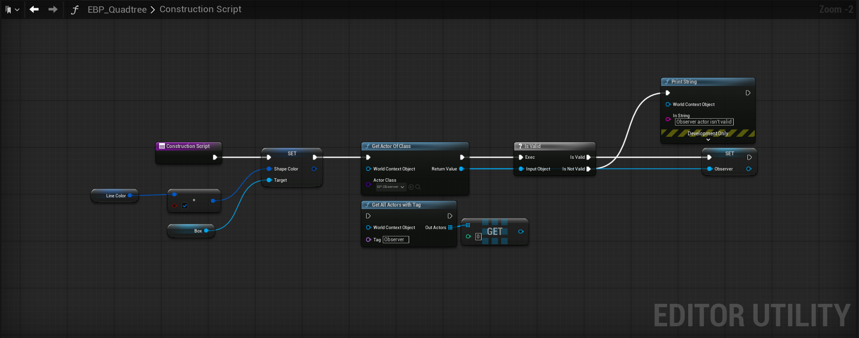
I've opted to use "Get Actor of Class", which returns the first actor of a given class that is present in your current level - so it's perfect for this visualizer as I know I will only have 1 observer actor in the scene at any given time. It's also acceptable to use "Get All Actors With Tag" here as well, as the out array will only have one entry, which you can then get a copy of. I went with the first method, but it's your life so do what you want. As a precaution, I check if the object reference is valid and if it is, cache it for later use. If it isn't, we print to string/log and continue. For the rest, I simply created a global linear color variable that is being used to set the box collision component color. We'll use the same color variable later to set the color value of our debug boxes.
Editor tick setup
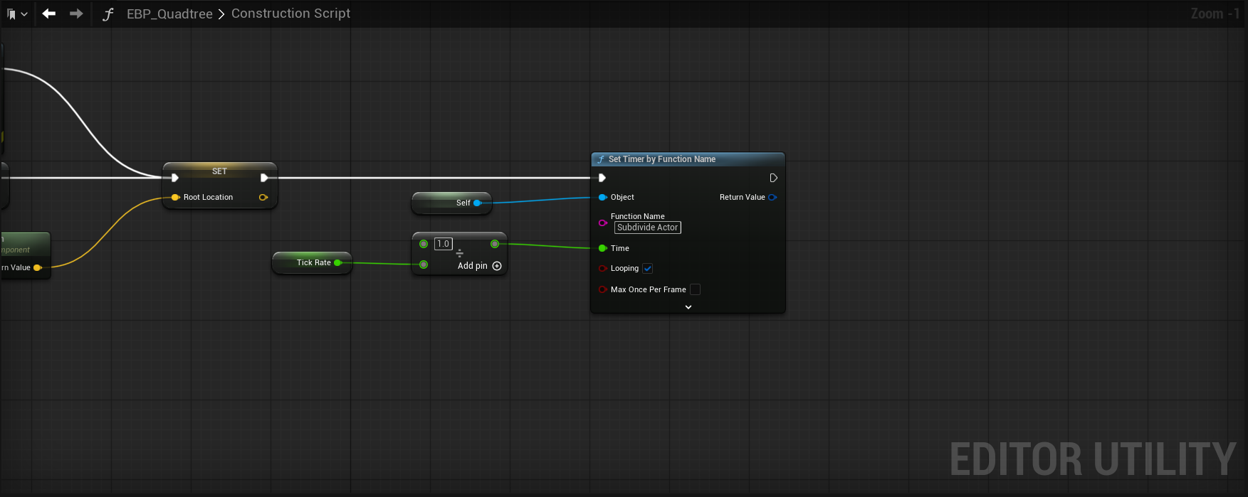
After that, we store our actors scene root component world location to a global variable, as we'll use that for initial quadtree calculation. With that out of the way, we come to the most important part to getting our editor actor to execute a function on tick - the "Set Timer by Function Name" node. We provide a global variable called "Tick Rate", and it's being passed into a divide node as the denominator. Why? Because while we think of tick rate as how many times per second we want updates, the timer node instead needs to know how many seconds to wait between those updates. So if we passed in 30.0f directly, it's going to wait 30 seconds to update, and we'll basically see nothing as we move our camera/actor around the quadtree; so we divide by 1 to get our small number to pass in and see things update accordingly. The last, most important piece of information to give to the timer node is the function name - you can type in whatever you want, but do keep note of it as we'll need to create a function with that name in the event graph. Also, make sure to set Looping to true and you're done with the construction script for now.
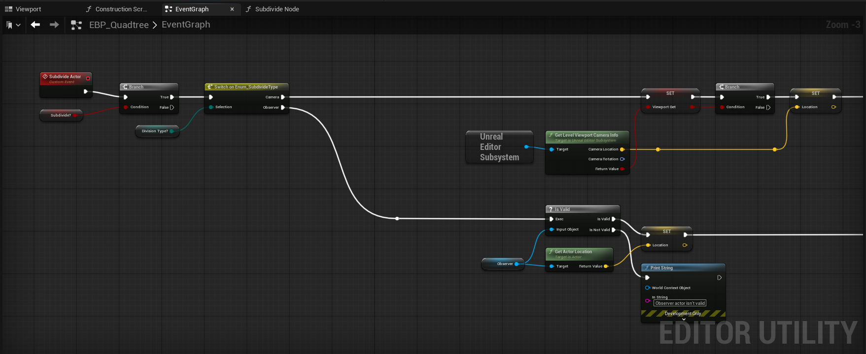
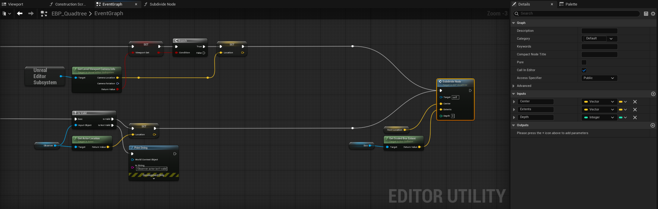
Now we're getting into the Event Graph portion of the blueprint, and things are going to get interesting from here on out. If you recall me saying that you should keep note of the function name you passed into the timer node, here is where you will need it. Right click in the graph and create a custom event - when it appears in the graph, give it the same name as you plugged into the timer node. What will happen is that your actor is going to execute the custom event at the tick rate we defined earlier. To verify this, you can plug up a print string node after your custom event and watch it spam the log/screen, or you can set a debug object (set it to itself) in the top bar of the blueprint tab to visually see the graph wires being executed (this will allow you to see the logic flow, too).
From here, a few things are happening - we create an instance editable variable called "Subdivide?" and plug it into a branch node. I set it up this way so that we can effectively disable our custom event should we want to at any point. Give this a category named "Quadtree" and you're good to go. You'll want to then create another instance editable variable called "Subdivision Type" (also has the Quadtree category) and it should be of whatever type you named your enum earlier. That gets passed into a switch on *insert enum type* that will have 2 output pins - one for camera and one for observer. We do this so we can split our logic into two paths (though they have the same final destination), so let's go with observer first.
In the observer path, we simply place down our Observer variable and check its validity once more; if it's valid, we store its Actor Location into a variable called "Location". If it isn't valid, we print out a string saying as much and stop.
In the camera path, we need to somehow be able to access the current viewport's camera, and the way to do that is through the "Unreal Editor Subsystem". Once you place that node down, you'll be able to pull off its output pin and search for "Get Level Viewport Camera Info". In my picture, I stored the return value before going into the branch, but you don't need to; if the return value is successful, we store the camera location into the Location variable I mentioned earlier. A quick note about the Unreal Editor Subsystem node is that even though were are utilizing an editor only actor, we cannot place that node into something like the construction script. The reason for this, according to my coworkers, is that "it's complicated". Anyway, moving on.
Into the matrix
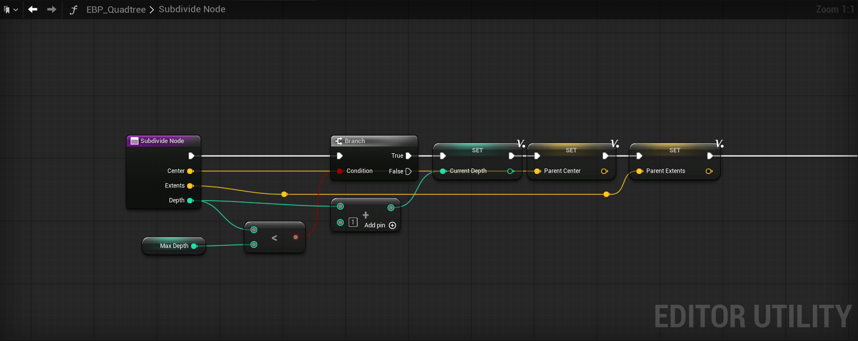
It is at this point that we arrive at the star of the show: our "Subdivide Node" function. This function will contain the logic needed to draw/create our quadtree.
Create this function and make sure it has the 3 requisite inputs as seen in my screenshot, and then we'll dive right in to some quadtree logic.
Our Subdivide Node has 3 inputs: Center/Extents/Depth. Why those things specifically? To start, we have to be able to track each quadrants center to be able to do a distance threshold check. If we're too far, we don't subdivide, and if we're close enough, we do. There's a little more to it than that, but we'll get there soon. So for what goes into these inputs in the top graph, we have our root location (this acts as the actor center, which is perfect for the first entry into the quadtree) and the box collision's extents. Depth can be left to 0 for the top graph.
So now we are going to break down the innards of the Subdivide Node step by step. To begin, one must understand that quadtrees are inherently recursion based, meaning that we are going to subdivide based on some criteria over and over until a threshold (Max Depth, in our case) is met. That behavior is going to dictate how we structure and pass our data around. Think of it this way - each region will set information that is used to generate its children (new regions), and those children will mutate that same information to generate new children until our threshold is hit.
Depth calculation
At the beginning of this function, we compare the node's Depth input to an instance editable variable called Max Depth. If Depth is less than Max Depth, we allow the execution to continue and if it's equal, we stop; should this comparison be left out entirely, recursion would just continue on and on and on and on until your PC has decided that its had enough and protests your bad decisions. Once we continue, we do Depth + 1 and store it into a local variable called "Current Depth". We do this because we are recursing and each level of recursion needs to increment the depth to have accurate information. This will make a little more sense in a bit.
We then store the incoming vector inputs as Parent Center/Parent Extents, respectively, as they will be used immediately after in our primary threshold calculation that determines if we create child nodes or not. What we have to do at this point is critical, which is logically think about what happens if we use the naive calculation of Distance(Location, Center) < Distance Threshold. If we do this only on the root, it will work just fine, and if your goal is to subdivide once, you can stop here - but what happens if we were to allow recursion with this calculation? If you answered "the closest half of the quadtree will recurse to max depth", you are correct.
So why does this happen? Let's say our root node center is 1000uu from the observer, and that passes our threshold check — so it subdivides. But here's the catch: anything before the center (i.e., closer to the observer) also passes that check. That means all child nodes on the near side will also pass, and the quadtree keeps subdividing in just that half, all the way to max depth. That's not what we want, so how do we fix this? We could try implementing some sort of threshold reduction based on our initial threshold value and depth level. The inherent issue is that our threshold value doesn't scale down between our levels of depth, meaning that our example of 1000uu is constant instead of being halved.
To address this, we need to figure out a formula that works automatically when changing depth levels, which means we will likely need to divide our Distance(Location,Center) value by Depth, somehow. If we do it naively, at the first depth level you'd have Distance Value/Depth(0), which results in a 0. So that fails immediately, and if we try to just let it continue (since depth does iterate per level) then we will likely still encounter issues since the first level is wrong. The next step would probably be to try Distance Value/Depth + 1, as that solves the division by 0 problem nicely. If you do this with a base value of 1000, then depth level 0 (the root level) is 1000/0+1 = 1000, which is correct. Depth level 1 is 1000/1+1 = 500.
At this point, it seems like we've figured it out, and while we are close, this is not the winning formula. On every 3rd depth level, we do not get a result that has been halved, and this is because we're using a linear formula to calculate our threshold value. To demonstrate: depth level 3 would be 1000/2+1 = 333.33. Depth level 5 would be 166.67. This isn't the biggest issue in the world, but when aiming for precision, we must aim to do better.
The pow() method
We can achieve perfect halving by putting current depth level into a power function where the base is 0.5, which is then multiplied by our Distance Threshold variable.
| Depth | Formula | Result |
|---|---|---|
| 0 | 1000 × 0.5^0 | 1000 |
| 1 | 1000 × 0.5^1 | 500 |
| 2 | 1000 × 0.5^2 | 250 |
| 3 | 1000 × 0.5^3 | 125 |
Simple recursive method
However, to avoid using pow() and take advantage of the recursion we are about to setup, you could simply add an extra input to the Subdivide Node function to pass in the Distance Threshold variable, and inside Subdivide Node, you'd do Distance Threshold*0.5. That value will get passed into Subdivide Node again (recursion, remember?) at the end of the graph, which will you give the exact same values as seen in the previous data table.
Extents as radius method
The setup I've gone with is something Christian Sparks (we talk about procedural generation a lot) theorized and I can confirm it works well. It is functionally identical but removes the Distance Threshold as a variable, if desired, which just means a little nicer on the UX side of things.
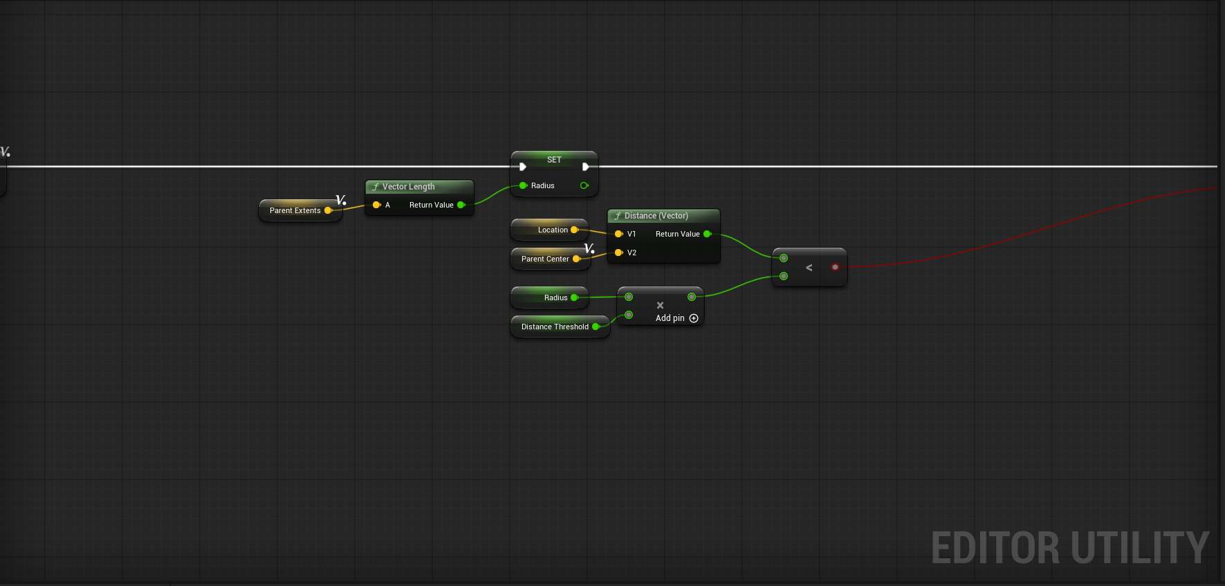
What this setup is doing is utilizing the parent extents we've already cached and calculating what is essentially a radius from it. How does taking the vector length from the box extents act as a radius though? Well, our extents give us the size of the box along each axis, which in our case we're using scaled extents, giving us 1000x1000x1000. From there, we need a single value that represents the size of the box in all directions, but how do we do that? The answer: entry level geometry.
Think about what we’re really doing: we’ve got our box extents, which are just the half-dimensions of the box along X, Y, and Z. If you imagine drawing a line from the center of the box to one of its farthest corners, that line would be the longest possible straight shot you could take from the center.
In geometry terms, this is half the space diagonal of the box. You can find it using the 3D version of the Pythagorean theorem:
r = √(x² + y² + z²)
We’re still finding the length of a hypotenuse (since our extents form a right triangle in each pair of dimensions), but in this case it’s the hypotenuse from the center to a corner, not corner-to-corner.
In the end, we are still doing what is effectively a distance threshold type check but where a value is automatically computed for us, meaning we can leave Distance Threshold at 1 and call it a day if we want. I've put together a small table here showing the values, which perfectly halve as we descend into the quadtree.
| Depth | Formula | Result |
|---|---|---|
| 0 | √(1000²·3) × 1.0 | ≈ 1732 |
| 1 | √(500²·3) × 1.0 | ≈ 866 |
| 2 | √(250²·3) × 1.0 | ≈ 433 |
| 3 | √(125²·3) × 1.0 | ≈ 216.5 |
Why are you showing multiple different methods for the depth calculation?
Because it's important to see how a given task can be approached from different perspectives, which is an important lesson for any developer, but especially so for tech artists.
Now I do apologize for so many explanations of that section, but it is really important to grasp in terms of how we traverse the quadtree, so I wanted to cover my bases.
The final pieces of the puzzle
After the comparison check, place down a sequence node with 4 outputs and get ready to implement the final part of the quadtree. We have to make our child nodes now, so create a new function called Create Node. I'll show you what it looks like, and you can recreate the input/output pins before we go further.
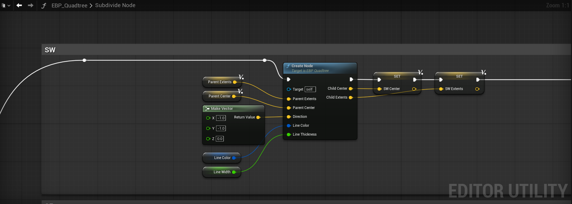
Before I show the innards, I want to explain the concept of what needs to happen here. When we pass the depth and distance/radius check, we need to create new child nodes, and for that to work, we must split all nodes that passed the check into 4 new nodes. Simple math can take us there; all you need are the parent extents, center and a direction.
Calculating child extents
The new extents are the easiest to calculate - you simply halve them in X and Y. So Child Extents = Parent Extents * FVector(0.5,0.5,0). Easy, right? Do this once, and it'll get you one of the 4 quadrants extents. To finish, we need the child center.
Calculating child center
To get the Child Center is a little more complicated, but not by much. This is where the direction input comes into play - we have 4 directions in total: SE, SW, NE, NW. Each of these directions are represented by a simple vector that is multiplied by our Child Extents and then is added to the Parent Center.
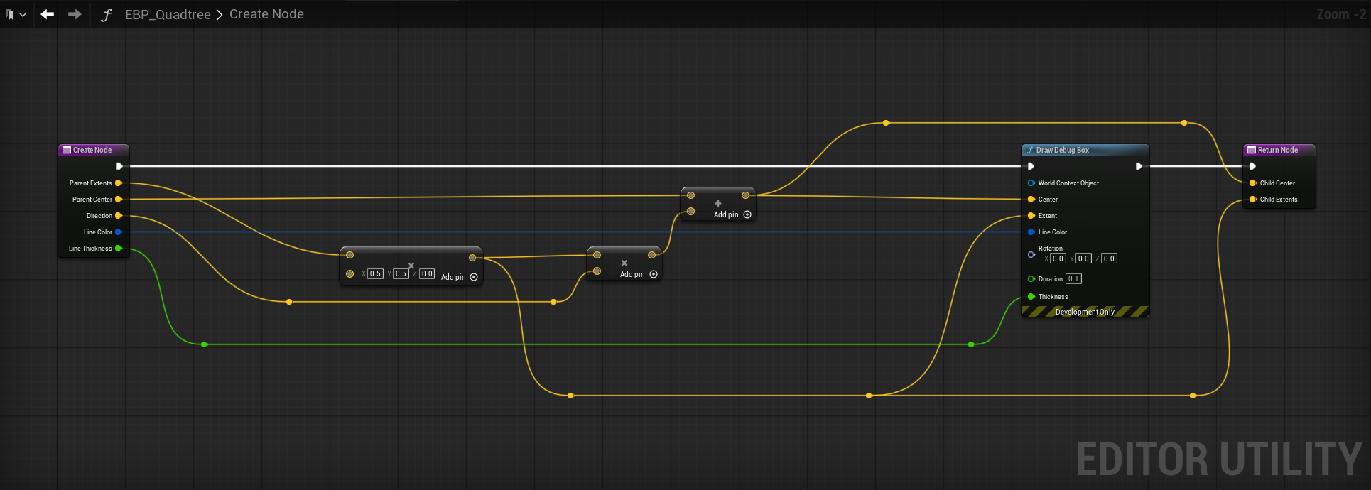
Further Breakdown of the Child Center Calculation
Each quadrant direction (SE, SW, NE, NW) tells us which way to move from the Parent Center to get to the Child Center.
The Child Extents are basically half the size of the child’s box in each axis.
Multiplying the direction vector (which is just ±1 in X and Y) by the Child Extents gives you the exact offset from the Parent Center.
Adding that offset to the Parent Center’s position drops you right in the middle of the child’s box.
Here is what all that looks like when combined.
Recursion time
We have reached the point where things may get weird, but that's okay. What happens next is that we place down a Subdivide Node function call...inside the Subdivide Node function definition. That looks like this.
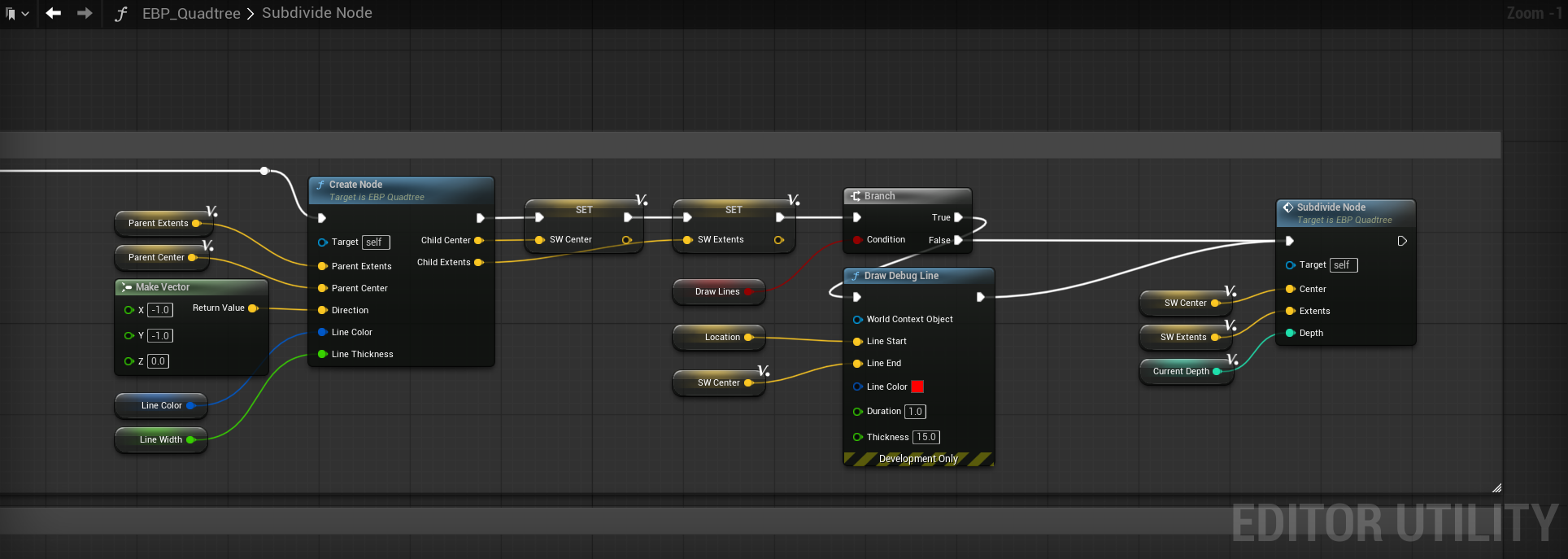
As you can see, we pass down the variables we just calculated into the Subdivide Node. Because we call the function inside itself, it acts as a loop, with only our depth check to stop it from infinitely recursing. With that out of the way, duplicate this chain 3 more times and make sure to give them the proper direction values and variables. Here is what that looks like.
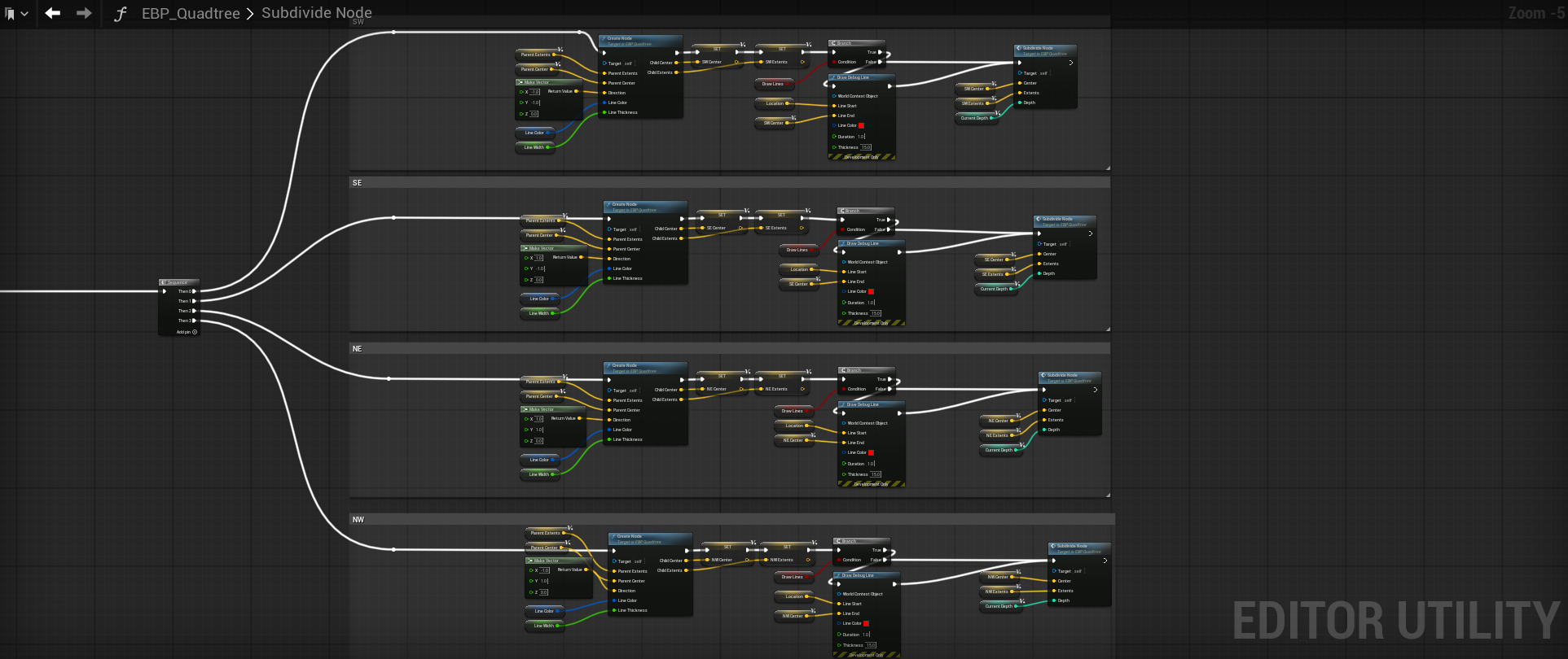
| Direction | Vector (X, Y, Z) |
|---|---|
| SE | (1, -1, 0) |
| SW | (-1, -1, 0) |
| NE | (1, 1, 0) |
| NW | (-1, 1, 0) |
You may have noticed the Draw Debug Line function call for each of those, and that goes along with the Draw Debug Box stuff for visualization. What this does is draw a line from the node center to the observer (don't enable this when in camera mode). I have this setup in the Event Graph as well before we call Subdivide Node.
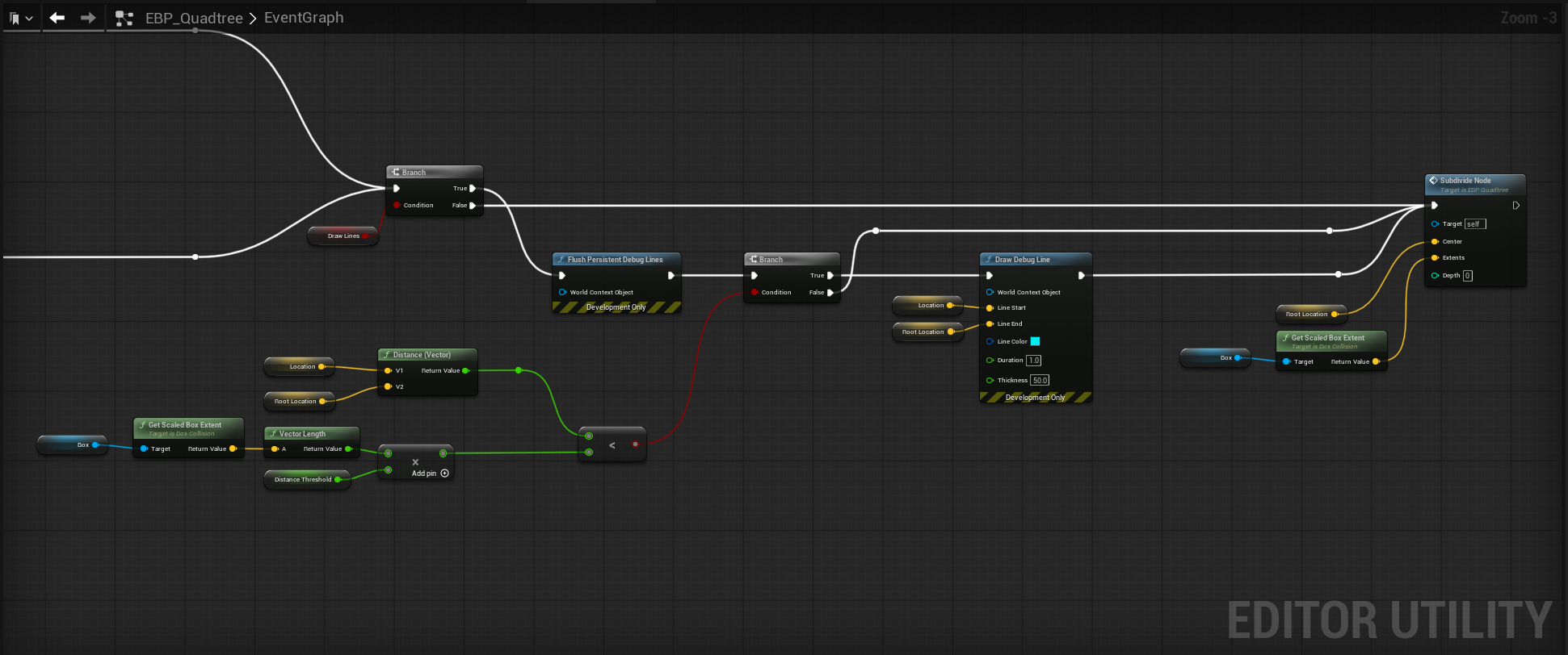
An important thing to note is my use of Flush Persistent Debug Lines - because we are drawing these boxes constantly, the Draw Debug functions can "accumulate" so to speak, because of their duration value. I set them all to 1.0 second so that they do render, and use the flush function makes them appear to update quickly.
Final results
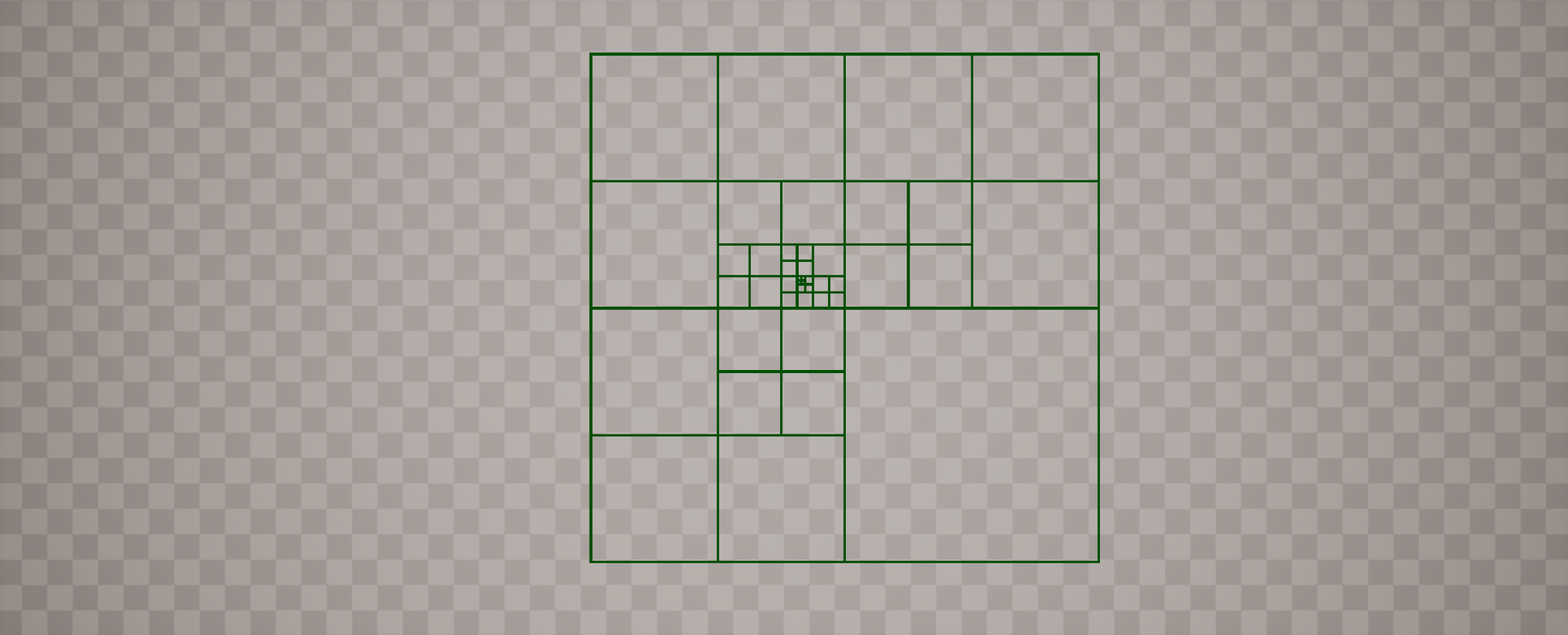
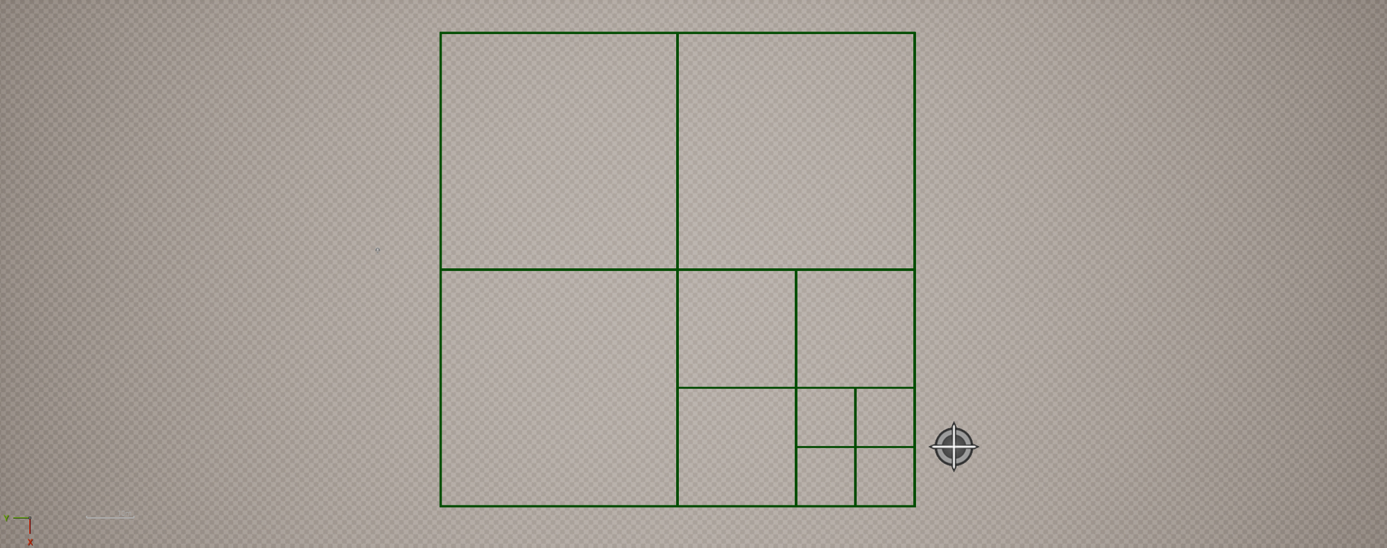
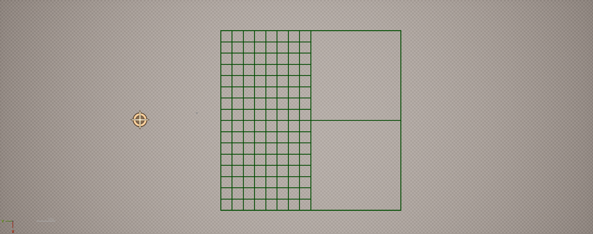
With all of the logic setup, here is the final output:
Demo showing camera and observer entering the quadtree.
Observer quadtree with draw line debug enabled
To keep things in perspective, this is a simple visualizer to help understand the basics of building a quadtree. We are not, however, tracking values between nodes, doing neighbor checks, etc, so this is purely a transient visualizer; things will get more complex once we go to integrate mesh generation with the quadtree logic.
8/14/2025 - I had someone on LinkedIn ask if it were possible to extend this to an octree, and the answer is of course. Takes about 2 minutes, as you just add 4 more children and move them up/down. It might be a naïve approach but it works.
Hard to capture this cleanly as there are a lot of nested boxes and PDI looks awful.
What's next?
This entry took a long time to come out, much longer than I would have liked. Between normal work burnout and rebuilding this site (I hope you all noticed), the planet stuff took a backseat. However, I have been more motivated than ever to work on it, and have at least the next 4 articles planned in advance. Things are going to kick into overdrive from here on out. Here, have a sneak peak at some of things we'll be implementing from the next 2-3 articles.

Until next time!